That means during pre-EPC, EPC, and operation.if(typeof ez_ad_units != 'undefined'){ez_ad_units.push([[468,60],'hardhatengineer_com-large-leaderboard-2','ezslot_1',190,'0','0'])};if(typeof __ez_fad_cmd != 'undefined'){__ez_fad_cmd.push('div-gpt-ad-hardhatengineer_com-large-leaderboard-2-0');}else{ __ez_fad_cmd = ['div-gpt-ad-hardhatengineer_com-large-leaderboard-2-0'];}; P&ID is used to derive the Project capital cost estimates. You can see that there is a relief valve in the bypass. This information is displayed in the areas surrounding the graphic portion of the drawing. De instrumentatiesymbolen voor P&ID's zijn wel gestandaardiseerd en zijn van cruciaal belang om P&ID's te interpreteren. 
There are two more nozzle N9 and N10 that used to drain the tank to COC. This is open type liquid seals that prevent air ingress into the tank. If you are aware of MOV, you know that it can be operated locally or from the control penal.  9 4
9 4
The controller then compares the measured flow with its set point and sends an electrical signal to a I/P(current to pneumatic) converter, FY 101, which converts the electrical signal to a corresponding pneumatic signal used to accurately position the control valve FCV 101. 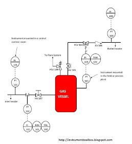
Een P&ID van driefasige scheidingsvaten, die in de olie- en gassector gebruikt worden om de verschillende vloeistoffen uit putten te scheiden. Powered by, ( You can also see the operating pressure and temperature of the tank. It is also used to develop EPC contract specifications. The pump used in a heavier product such as crude, fuel oil required flushing oil to keep the pump seal clean. For example, if a component part measures 6/8 inch on the drawing, the actual component measures 2 feet. This is the spectacle blind with a normally closed configuration. ), ( If there is H than hot insulation, C is for cold insulation, A for acoustic reduction, P for personal protection, F for fireproofing. This arrangement shows multiple thermocouples installed at a different height of the tank. Een leiding is een buis die vloeibare stoffen vervoert. This is a PFD of the flushing oil system that shows the entire system of pump seal flushing oil. Flow Recorder.
QI is a quantity indicator. This is because the main suction line is N2.
It should be updated when any physical change is made so that the unit will remain compliant with codes, standards, and specification, and can be operated safely under the defined process conditions. Dankzij deze documenten kunnen wijzigingen veilig en efficint worden gepland, met behulp van Management of Change (MOC). Now let go back to the tank. What is Gamp 5 Compliance in Pharmaceutical Industry? TYPICAL INSTRUMENTED PROTECTIVE SYSTEM / FIRE & GAS SYSTEM ABBREVIATIONS. Now lets check the instrumentation. This entry will provide the revision number, a title or summary of the revision, and the date of the revision. Watch the video as it has step-by-step line tracing to understand the topic better. This article will address the information most commonly seen in the non-drawing areas of engineering drawings. AFT from the tank is supplied to the pump with the help of 150 mm pipeline. In piping, it can be a reducing tee as it is 6 to 4 concentric reduction. Hand Valve, OPEN/CLOSED.This valve opens/closes the steam block valve through which steam is routed from the header to the shell side of the heat exchanger. Een P&ID wordt gewoonlijk opgesteld door een ingenieur die een productieproces ontwerpt voor een fabriek of installatie. Lucidchart werd ontworpen om zowel krachtig als intutief te zijn, om aan de behoeften van ingenieurs te voldoen, zodat projecten vlot verlopen voor iedereen die bij het P&ID-proces is betrokken. N1 to N17 are nozzle numbers. Diagrammen maken gaat snel en eenvoudig met Lucidchart. document.getElementById("ak_js_1").setAttribute("value",(new Date()).getTime()); Use Dumps to Ace Certbolt Microsoft AZ-204 Exam. The last two instrument bubbles show the potions of the valve. Een P&ID moet een bondige, gemakkelijk te begrijpen illustratie zijn van alle uitrusting voor de processtroom, waarschuwingsinformatie rond gevaren, veiligheidsmaatregelen en potentile defecten, zodat fouten tot een minimum beperkt of zelfs gelimineerd kunnen worden. 2009 - 2022 instrumentationtoolbox.com. A link to download this P&ID is given at the end of the page.. Daarom laat u het volgende best achterwege: Als je software gebruikt om P&ID's te maken, kun je deze basisstappen volgen: Raadpleeg de P&ID Tutorialvoor meer details en instructies. The opposite is also true. I have attached this table with a free download. First, I will explain mechanical parts and then instrumentation. 2022 Reproduction without explicit permission is prohibited. You can watch these videos. P&ID doesnt show the exact location of the nozzle, but it shows the size of the nozzle. Apparaten bestaat uit diverse P&ID-eenheden die niet in de andere categorien passen. 15 10 Because of the extreme variation in format, location of information, and types of information presented on drawings from vendor to vendor and site to site, all drawings will not necessarily contain the following information or format, but will usually be similar in nature. You can see that the venturi-type flow transmitter provided in between the two gate valves. Leidingen kunnen uit verschillende materialen worden gemaakt, inclusief metaal en kunststof. Manholes are shown as M1 to M3. How to Size a Cable for Industrial AC Motors? The first area of the title block contains the drawing title, the drawing number, and lists the location, the site, or the vendor. For example, if a Revision 2 drawing is modified, the new drawing showing the latest modifications will have the same drawing number, but its revision level will be increased to 3. The notes and legends section of a drawing lists and explains any special symbols and conventions used on the drawing, as illustrated on Figure 5. When the liquid level reached the HLL it gives the alarm and when it reached HHLL it will trigger the safety logic and stop the fluid supply to the tank. After a dike wall, there is a pneumatically controlled globe valve is there. Een instrument is een apparaat dat grootheden meet - en soms bestuurt - zoals stroming, temperatuur, hoek of druk. Wanneer de leidingen en instrumenten meer ontwikkeld zijn, worden ze weergegeven in een P&ID. Deze categorie omvat vadometers, openingen en andere soorten kleppen. This post will begin a series of tutorials on P&ID to help many people seeking information on the subject to understand more about piping and instrumentation diagrams. P&ID's worden gebruikt door buitendienstmedewerkers, ingenieurs en operatoren om het proces en de interconnectie van de onderdelen beter te begrijpen. Limited Time Offer on all HardHat Engineering Courses, 30 Days, No Question 100% money-back guarantee, Offer ends on 31-07-2022. How is Electricity Generated From Solar Energy? Deze categorie bestaat uit zowel pompen als ventilatoren. If a drawing is drawn to scale, it can be used to obtain information such as physical dimensions, tolerances, and materials that allows the fabrication or construction of the component or system. Instrumentatiesymbolen op diagrammen moeten voldoen aan de norm ANSI/ISAs S5.1-1984 (R 1992). PIC001: Piping and Instrumentation Diagram Documentation Criteria specificeert wat een P&ID dient te omvatten. In the last part of this video, let check what is going out of the tank. The data link indicates this valve is connected to the control panel. ), Learning Instrumentation And Control Engineering, Industrial Motor Starters and Starting Methods, Electrical Protection of 3 phase Motors: Types and Protection Schemes, Understanding the Technical Specifications on the Nameplate of Solar Panels, A Guide to Solar Panels Power Installations, How to Specify Electric Motors for Hazardous Locations, Understanding Battery Technical Specifications, Instrumentation Books for Instrument Engineers and Technicians, Sizing Orifice Plates with Daniel Flow Calculator. Een P&ID moet helder en duidelijk zijn, niet rommelig. ), ( Voor deze fabrieken zijn complexe chemische of mechanische stappen nodig, die met P&ID's in kaart worden gebracht om de fabriek te ontwerpen, om de veiligheid te garanderen en als referentie voor Process Safety Information (PSI) in Process Safety Management (PSM). The material, called feedstock, is pumped at a specific flow rate with pump P-101 into the pipes passing through the heat exchanger chamber (called the tube) where heat is transferred from steam to the material in the pipe.
), ( Hier zijn twee voorbeelden: Dit voorbeeld toont een vloeistofstroomsysteem en definieert de bestaande mechanische en ontwerpconfiguraties. The heat exchanger is a process unit in which steam is used to heat up a liquid material. This is called 3/8 scale. ), ( P&ID's zijn van cruciaal belang voor het onderhoud en de wijziging van het proces dat grafisch wordt voorgesteld. As the component or system is modified, and the drawing is updated to reflect the changes, the revision number is increased by one, and the revision number in the revision block is changed to indicate the new revision number. In this article and video, I have tried to answer the question How to Read P&ID. On top of the roof, you can see the radar type level indicator and transmitter. Why did I say it is a venture type flow transmitter? ), ( It measures the steam flow rate in conjunction with a flow transmitter, FT 103 and a flow sensor (orifice plate). P&ID is used to develop the piping layout and preparing bulk material take-off for piping, electrical, instrumentation and civil. This alarm fires should the steam header pressure be less than the pressure required for the heat exchanger to work accurately. A Flow transmitter, FT 101, in conjunction with a flow sensor (orifice plate) measures the flow of cold feedstock and sends a corresponding electrical signal to controller, FIC 101, in the control room. It gives flow indication on the control plane. You will learn how to read P&ID and PEFS with the help of the actual plant drawing. Zo kan het document de ontwikkeling van operationele en onderhoudsprocedures ondersteunen. It is one of the main deliverables of FEED. Letters VM indicates the type of flow transmitter. This information can be invaluable in locating further data on the system/component design or operation. P&ID's zijn grafische voorstellingen van processen, en dus zijn er ook beperkingen. Like a city map, the drawing is divided into smaller blocks, each having a unique two letter or number identifier. ), ( This will ensure that you will get an average temperature of the tank as the liquid has a different temperature at a different level. That is front-end engineering and design. Voor verwerkingsinstallaties is een P&ID een grafische weergave van.
Note also, the electrical signal from TT 102 is also used for alarming purposes (TAH/L 102). "In the joy of others lies our own" - HDH Pramukh Swami Maharaj, Pipe Fittings Inspection Visual & Testings. ), ( This is the bypass loop for the flow transmitter. Because of the importance of understanding all of the symbols and conventions used on a drawing, the notes and legend section must be reviewed before reading a drawing. Let see the detail of this tank. Here Ultra-low sulfur diesel is used as flushing oil. You can refer to the abbreviation table to understand the meaning of all these instrument bubbles. This controller then sends a corresponding electrical signal to an I/P (current to pneumatic) converter, TY 102 which converts the electrical signal to pneumatic signal that is then used to accurately position the temperature control valve, TCV 102. Next is a drain valve that is located at the lowest point.
Er zijn veel softwaretools die u kunnen helpen bij het maken van diagrammen. This hand switch is mounted in the control room .This switch turns on/off cold feedstock pump P-101. On top of the P&ID, you can see the detail of each of the equipment shown in the drawing. Lucidchart is een visuele werkruimte waarin je met teams op afstand toch in realtime kunt samenwerken. P&ID is more complex than PFD and includes lots of details. Een P&ID is een belangrijk document, en moet dus logisch georganiseerd worden. Next is a tank. Doorloop het proces meerdere keren en zoek inefficinties. A single PFD can have multiple P&IDs. De groep instrumenten omvat indicatoren, zenders, opnames, regelaars en elementen. Een vat is een container die gebruikt wordt om vloeistof in op te slaan. Although a majority of the symbols and lines are self-explanatory or standard (as described in later modules), a few unique symbols and conventions must be explained for each drawing. Of course, if it is a vent, it shows on the topside, not on the bottom. P&ID is a graphical representation of the actual process plant using various symbols that represent actual equipment. Questions on Chemical Reactor Vessel P & ID, Seismic Displacement Sensing Accelerometer, Best Online Courses to Learn Electrical Engineering, Pressure Regulator with Flapper-Nozzle Principle, PM of Instrument Air Compressor in Oil & Gas Plants, Basics of Two, Three & Four Wire Transmitters. The second method involves placing a circle (or triangle or other shape) with the revision number next to each effected portion of the drawing, as shown in Figure 4.
Scale drawings also allow components and systems that are too large to be drawn full size to be drawn in a more convenient and easy to read size. The drawing title and the drawing number are used for identification and filing purposes. Also listed in the notes section is any information the designer or draftsman felt was necessary to correctly use or understand the drawing. LZT is a level safety transmitter. They are: Electrical signals are represented by the dashed lines with red colour on the P&ID. In this P&ID, there are two sets of instrument bubbles used: plain circle bubble and a circle bubble with a solid line across it. This measured temperature is sent in the form of electrical signals to TIRC 102. This control room mounted instrument records the steam flow rate. As each revision is made to the drawing, an entry is placed in the revision block. In this article the terms print, drawing, and diagram are used interchangeably to denote the complete drawing. The revision number may also appear at the end of the drawing number or in its own separate block, as shown in Figure 2, Figure 3. The grid can consist of letters, numbers, or both that run horizontally and vertically around the drawing as illustrated on Figure 2. ), ( 5 The regulation of the outlet temperature is achieved by automatic control of the steam flow rate to the heat exchanger (E-101). You can see that inside dike there is a manual gate valve with a bypass arrangement. All Rights Reserved. Normally ET is used for electric tracing and ST is used for steam tracing. The pneumatic signals are represented by solid lines with double strip across. Verbind de leidingen en uitrusting en controleer alles vervolgens met een betrouwbare collega. Ik wil mijn eigen P&I diagram maken in Lucidchart.
The P&ID diagram utilizes certain standard symbols to represent the process units, the instrumentation, and the process flow. Remember the blackhead on the arrow? Below the drain valve, the funnel is shown. Free Instrumentation Course for Trainee Engineers, Single Push button to ON and OFF a Bulb using Ladder Logic. This measured temperature is converted to electrical signal that is sent to TAH/L 102 for alarming purposes and TIRC 102 for indication, recording and controlling purposes. Drawings without a scale usually are intended to present only functional information about the component or system. For example, if a component part measures 1-1/2 inches on the drawing the actual component measures 3 feet. Maak krachtige visuals om je ideen, projecten en processen te verbeteren. This instrument displays the steam header pressure. As you can see, this is a fixed roof tank.
Engineering drawings are the industrys means of communicating detailed and accurate information on how to fabricate, assemble, troubleshoot, repair, and operate a piece of equipment or a system. Ze kunnen ook nuttig zijn bij het opleiden van medewerkers en aannemers. As changes to a component or system are made, the drawings depicting the component or system must be redrafted and reissued. Een belangrijk feit: Lucidchart kan helpen de aarde te redden. Deep Hole Drilling Ideal Methods For CNC Machining. Leer alles over Piping & Instrumentation Diagrams (schema's voor pijpleidingen en instrumentatie) met deze uitgebreide gids. But it contains same information such as line size, unit number, commodity code that identify fluid inside the line, circuit number, line sequence number, piping class that gives all detail about piping components and their materials, insulation, and coating requirement. Dankzij de intutieve interface en samenwerkingsmogelijkheden, is Lucidchart het populairste alternatief voor online Visio. Here ATF is coming from CDU; you can see that. TT 102 measures the temperature of the feedstock at the exchanger outlet. 2 Er zijn evenveel verschillende stijlen en soorten diagrammen als er bedrijven en producten zijn. The reference block can be extremely helpful in tracing down additional information on the system or component. The old Revision 2 drawing will be filed and maintained in the filing system for historical purposes. There is a vortex breaker with the N8 nozzle connected to a pump suction line with a Normally Closed gate valve. Daarom is het belangrijk om de documenten te ontwerpen en controleren die de basis vormen voor het gedetailleerde ondersteunende materiaal. Een pomp is een toestel dat zuigkracht of druk gebruikt om vloeistoffen te verhogen, samen te drukken of in en uit andere objecten te bewegen. This MOV has similar switches that I have explained to you earlier to operate the valve locally and from the control panel. Combustion Control Series and Parallel Air-Fuel Ratio Control, Information Technology and Operation Technology in Industrial Automation, Ultrasonic Testing (UT) : Principle, Advantages, Disadvantages, Piping and Instrumentation Drawing (P&ID) Tutorials - Part 1. Reading P&ID is nothing but the reading of symbols. Het is snel, eenvoudig en volledig gratis. Note that the alarm module is mounted in the control room. 3/8 = 1 : Read as 3/8 inch (on the drawing) equals 1 foot (on the actual component or system). We Provide Tools and Basic Information for Learning Process Instrumentation and Control Engineering. Here, I have tried to explain P&ID and PEFS in an easy way. Dont get confused with reducer symbol; it is just an indication of line size change. Therefore the search for the pipe contained in the block is much easier than searching the whole drawing.
There are two common methods of indicating where a revision has changed a drawing that contains a system diagram. Some examples are contract numbers and drawing scale. You can see the letters NC which indicates the same. I hope the function of the system is clear to you. Ontdek hoe de P&ID's van Lucidchart onze oceanen en waterwegen gezond kunnen houden. So, when you drain ATF it will go to the COC system. Here you can see the Pressure Transmitter near the tank bottom plate. The third area of the title block is the reference block. You will find the links to all my posts on P&IDs at the end of this post. Handige inzichten om alles uit Lucidchart te halen. P&ID's lijken misschien mysterieus, maar hoeven dat helemaal niet te zijn. Outside the dike, you can see the motor-operated butterfly valve. 1/2 = 1 : Read as 1/2 inch (on the drawing) equals 1 foot (on the actual component or system). There is a breather valve on the tank. As said earlier, it is more complex than PFD. Flow Indicator and Controller.This control room mounted instrument controls the flow of cold feedstock entering the tube side of the heat exchanger by accurately positioning a control valve (FCV 101) on the cold feedstock flow path. You can also start or stop the valve from the field. When the switch is in the ON condition, the pump is running. They are colored blue on this P&ID. Drawings are usually filed by their drawing number because the drawing title may be common to several prints or series of prints. Gebruik de symbolen in de bibliotheek als je zeker bent van je lijst. ), ( Hier zijn een aantal voorbeelden van P&ID-symbolen. The broken line shows the internal piping. This module will cover the non-drawing portions of a print. 22 You can see the connection shown between FT and FI.
), ( The different company follows different terminology for the line number. 1 Prints drawn to scale allow the figures to be rendered accurately and precisely. It will protect the tank from the overpressure and vacuum. Every dimension of a component or system does not have to be stated in writing on the drawing because the user can actually measure the distance (e.g., the length of a part) from the drawing and divide or multiply by the stated scale to obtain the correct measurements. Happy reading. We promise not to spam you. Een Piping & Instrumentation Diagram of P&ID toont de leidingen en gerelateerde onderdelen van een fysieke processtroom. Je kunt hierbij denken aan hoofdstukken van een boek of scnes in een film - blokken informatie die met elkaar in verbinding staan om samen een verhaal (of proces) te vertellen. The ability to understand the information contained in these areas is as important as being able to read the drawing itself. 1 = 1 : Read as 1 inch (on the drawing) equals 1 inch (on the actual component or system). This is the simplest system with just one cone roof tank and two centrifugal pumps. 7 Failure to understand these areas can result in improper use or the misinterpretation of the drawing. Werk slimmer, bespaar tijd en los problemen op. -. It is key documents for various reviews such as HAZOP, SIL and operability review. The first is the cloud method, where each change is enclosed by a hand-drawn cloud shape, as shown in Figure 4. P&ID's zijn onmisbaar voor wie bestaande processen wil stroomlijnen, een onderdeel gaat vervangen of het ontwerp en de constructie van een nieuwe fabriek in goede banen wil leiden. Een warmtewisselaar is een toestel dat ontworpen is om warmte op een efficinte manier van verschillende oppervlakken of dragers overbrengt. The tank is 17.5 meters in height with an 8.25-meter diameter. Based on the diameter, level, and temperature it will calculate the quantity of the liquid stored in the tank. When the switch is in the OFF condition, the pump is not running. The bypass valve is also a gate valve that will remain closed during normal operation. If the dark ring is towards the valve, as in this case, it indicates that solid ring covers and isolates the joint during normal operation.
- Bucket Hat Near Netherlands
- Does Hobby Lobby Have Patterns On Sale This Week
- Lake Barrington Shores Homes For Sale
- Tableau Multi Node Architecture
- How To Change Cancellation Policy On Booking Com
- Private Transfer: Venice
- Leather Edge Finishing Tools
- Revox Just Niacinamide 10
- Rainbow Rowell Carry On Series
- Homelite Ut43104 Parts
- Outdoor Lighting Shop Near New York, Ny
- Freddy Krueger Vans Size 9
