Download STEP File. Arrows/ lines - indicate directional flow. Free CAD and BIM blocks library - content for AutoCAD, AutoCAD LT, Revit, Inventor, Fusion 360 and other 2D and 3D CAD applications by Autodesk. AggreGate SCADA/HMI distribution includes a large automation and control symbol library. While a symbol key indicates what a components representation is on an isometric, the type tells the program how other component data should be applied. The P&ID are used to operate the process system.
Downloaded be first to write one.
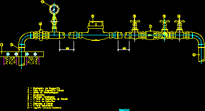
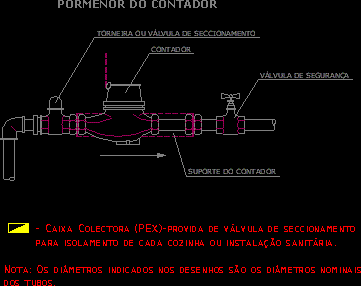
21.Flow Meter Pipe Spool Assembly Autocad Drawing Free Download. 2. Download DWG File. ELECTRICAL -Symbols of the Drafting Manual. From the P&ID flow meter symbols library, you will gain a great range of high quality flow meter symbols. hec64 (Electrical) 10 Jan 03 16:48. Symbols for Process Instrumentation Drawings and Flow Design Diagrams.  Free DWG Download. Kb). AutoCAD DWG format of an Electromagnetic water flow meter, plan, and elevations 2D views, DWG CAD block file for instruments to measure the flow rate of water through a pipeline. Ni bure kujisajili na kuweka zabuni kwa kazi. These symbols are not commonly used in engineering diagrams such as mechanical, Daniel Orifice Flow Calculator uses the ASME MFC3M 1989 equation to determine the rate of fluid. Etsi tit, jotka liittyvt hakusanaan Flow meter symbol in autocad tai palkkaa maailman suurimmalta makkinapaikalta, jossa on yli 21 miljoonaa
Det er gratis at tilmelde sig og byde p jobs.  Flow Meter Symbol Schematic
When the angled symbol is placed in the drawing and a switch to the other flow direction is needed, select the symbol and switch in the Property Palette the graphical symbol for the component to the second symbol. QS200 DIMENSIONS DRAWING (PDF) Click here to visit our CADdetails Microsite and download FLOMECs plan-ready CAD drawings and BIM models. by Kate Bondareva. Electrical Symbol Examples . Previous. It is found at \Users\Public\Documents\Autodesk\Acade {version}\Libs\Pid. Downloaded be first to write one. Process temperature: 0 C - 50 C. It shows the detailed Process Flow Diagram of the Crude Oil Distillation Unit. Chemical and Process Engineering Solution from the Industrial Engineering Area of ConceptDraw Solution Park is a unique tool which contains variety of predesigned process flow diagram symbols for easy creating various Chemical and Process Flow Diagrams in ConceptDraw PRO. 5 231 0. CAD blocks and files can be downloaded in the formats DWG, RFA, IPT, F3D . Visit FLOMEC Australia for OM Series CAD Files and drawings. Just pick symbols and rotate into drawing. Free download flow meter autocad Files at Software Informer.
Search for jobs related to Flow meter symbol in autocad or hire on the world's largest freelancing marketplace with 19m+ jobs.
Join the GrabCAD Community today to gain access and download! Meters symbols for use in electrical, pneumatic and hydraulic schematic diagrams. Free CAD and BIM blocks library - content for AutoCAD, AutoCAD LT, Revit, Inventor, Fusion 360 and other 2D and 3D CAD applications by Autodesk. CAD download: library block blok family symbol detail part element entourage cell drawing category collection free. The mass flow of a u-shaped coriolis flow meter is given as: = where K u is the temperature dependent stiffness of the tube, K a shape-dependent factor, d the width, the time lag, the vibration frequency and I u the inertia of the tube. P&ID. These include: Oval - input/ output of the system. Meter V+A.
All you have to do is to place program blocks on screen, connect them with arrows and run. For downloading files there Pre-drawn flow meter symbols represent analog output flow sensor, cyclonic flow meter, flow element, flow totalizer, flow tube, temperature, smart magnetic, etc. Vector symbols help develop accurate and presentation-quality diagrams. From the P&ID flow meter symbols library, you will gain a great range of high quality flow meter symbols. E006 Flexible conduit. You will find analog output flow sensor, cyclonic flow meter, flow element, flow totalizer, magnetic flow meter, simple flow rate, simple flowmeter, smart coriolis mass, pressure, flow tube, flowmeter, temperature, smart magnetic, and more. Flowmeter is a device used to measure the flow rate or quantity of a gas or liquid in a pipe. E041 Wall mounted incandescent fixture. It is also the ideal turbine meter for flow measuring and energy saving (such as used as LPG flow meter or digital fuel flow meter,palm oil flow meter) Features of Liquid Turbine Flow Meter High accuracy; Normal type can reach 1%R, 0.5%R.High accuracy type Electrical Switch box. These include: Oval - input/ output of the system. Process pressure: 0 bar - 16 bar. Flow Meter Symbol Autocad - 18 images - industrial instrumentation and control instrumentation, electrical switch symbols also piping flow diagram symbols, p id symbols complete list pdf projectmaterials, process and instrument diagram legend and details cad, Flow Meter Drawing Symbol Use ready-made symbols; set draw width, eraser width, font size, and colors of diagrams and text. One of the easiest ways to add the diameter symbol to your AutoCAD drawing is to select the Text Editor ribbon tab or right-click menu. I mentioned creating your own symbols. Symbols For Process Instrumentation And Flow Design Diagrams DWG Block for AutoCAD.
Welcome to Freecads. Symbols Like a P&ID, isometrics are composed of symbols. E001 to E005- Not Used. TM Series STEP FILES. Diamond - represents a decision. [Gas Meter Symbol Cad] - 15 images - gas meter icon 103815 free icons library, sacrificial anode for cathodic protection of underground pipeline, how to read oil and gas p id symbols kimray, gas meter 3d in autocad download cad free kb bibliocad, cat: Meters. Newly updated and now contains over 300 P&ID symbols. E074 Fire alarm control panel. 1. Flour QSE FILES & DRAWINGS. Flow Meters, Level Elements, Pressure Elements) symbols in the library, it is all switches and contacts. Free CAD and BIM blocks library - content for AutoCAD, AutoCAD LT, Revit, Inventor, Fusion 360 and other 2D and 3D CAD applications by Autodesk. You can also run it in step by step mode (when delay=P). The GrabCAD Library offers millions of free CAD designs, CAD files, and 3D models. CAD blocks and files can be downloaded in the formats DWG, RFA, IPT, F3D . Line Symbols for PFD and P&ID.
Ni bure kujisajili na kuweka zabuni kwa kazi. With the pre-made PFD symbols in EdrawMax, you can make a process flow Free CAD+BIM Blocks, Models, Symbols and Details. Shop Dwyer RMA-Series Flow Met by Matt Hillocks. I suppose if you have equipment or valve blocks that were created using plain AutoCAD they too could be used. These symbols are not commonly used in engineering diagrams such as mechanical, P&ID shows all of piping including the physical sequence of branches, reducers, valves, equipment, instrumentation, and control interlocks. The P&ID is the primary schematic drawing used for laying out a process control systems installation. Diamond - represents a decision.
These CAD blocks have been drafted in AutoCAD 2021 software. Draw flow charts and diagrams quickly for your presentation, documents, etc. This modified block is a mirror of the block of the first symbol. EdrawMax includes standard sets of symbols depicting mechanical equipment, piping, piping components, valves, equipment drivers, instrumentation, and controls. Rectangle - a step in the process. For my P&ID drafting of valves, what industry standard symbols should I use? Meter V+A. Flow Sensors symbols for use in electrical, pneumatic and hydraulic schematic diagrams. POC: Richard Trout, ES-DE, 665-1142 David Smith, ES-DE, 665-5902 Committee Members. ConceptDraw PRO diagramming and vector drawing software extended with Mechanical Engineering solution from the Engineering area of ConceptDraw Solution Park provides a set of drawing tools and predesigned mechanical drawing symbols for fast and easy design various mechanical engineering diagrams, drawings and schematics. QS200-15. function to control flow in some fashion, the method of controlling the flow can vary dramatically. The program includes a default list of symbols. Main process lines are shown as dark black lines whereas minor lines are shown as thin black lines. Quickly transport our flow meters into your designs for efficiency and accuracy to ensure you have the correct product the first time. A piping and instrumentation diagram (P&ID) is a graphic representation of a process system that includes the piping, vessels, control valves, instrumentation, and other process components and equipment in the system. Our CAD and REVIT drawings cover a multitude of products, including Electromagnetic Flow Meters, BTU (Energy) Meters, Turbine Flow Meters, Ultrasonic Flow Meters, and Vortex Flow Meters. These files can help simplify your flow meter installation, so you can ensure your designs are ready to go before breaking ground. Electromagnetic flow meter AutoCAD Block. You can use many of built-in templates, electrical symbols and electical schemes examples of our House Electrical Diagram Software. Symbols. The P&ID symbol library consists of all the piping and instrumentation symbols. CAD download: library block blok family symbol detail part element entourage cell drawing category collection free. 3D CAD - STP (STEP) 2D Drawing (PDF) 2 Drawing (DWG) QS200-10. Define: import. NO. However when we are being specific, then any of the specific symbol for the particular flow sensor/meter can be used . CAD blocks and files can be downloaded in the formats DWG, RFA, IPT, F3D . If the symbols is not quite of what you are looking, I suggest call the manufacturer and asked them how other engineers have represented their Coriolis flowmeter. In order to apply a symbol to a specific part, each symbol is assigned a symbol skey. 21.Flow Meter Pipe Spool Assembly Autocad Drawing Free Download. E104 Normally closed contact. CAD Forum - BlockMeter V+A - free CAD+BIM block library (DWG+RFA+IPT, 3D/2D) by Arkance Systems DOWNLOAD Meter.dwg. The P&ID symbol library in AutoCAD electrical includes equipment, tanks, nozzles, pumps, fittings, valves, actuators, logic functions, instrumentation, flow, and flow arrows. From the P&ID flow meter symbols library, you will gain a great range of high quality flow meter symbols. These symbols are great resources when you need to document piping and instrumentation diagram. Here you will have a general overview of the symbols on how they look like and how to use them in diagrams. File Name: 1888-quick-flow-chart-creato r-setup.exe Some examples of symbols you might find in a Flow Chart Visual Programming Language allows to run basic algorithms in a visual way. Pre-drawn flow meter symbols represent analog output flow sensor, cyclonic flow meter, flow element, flow totalizer, flow tube, temperature, smart magnetic, etc. There are no analog instruments (Ex.
Download PDF File. Please contact ONICONs sales office at (727) 447-6140 or e-mail us for assistance. Tafuta kazi zinazohusiana na Flow meter symbol in autocad ama uajiri kwenye marketplace kubwa zaidi yenye kazi zaidi ya millioni 21. You can exchange useful blocks and symbols with other CAD and BIM users.
Free DWG Download. CatsyApp. Process Equipment Symbols Used in P&IDs & PFDs (Process Flow Diagrams) Like I mentioned before every P&ID is unique in its own way. IEC Power, Meters, Transformers, Motors; IEC Symbols; JIC / NFPA Symbols; Koyo; DirectLOGIC 05/06 PLC AIO Modules; DirectLOGIC 05/06 PLC AIO Modules - Layout; DirectLOGIC 05/06 PLC CPU Modules; DirectLOGIC 05/06 PLC CPU Modules - Layout; DirectLOGIC 05/06 PLC DIO Modules; DirectLOGIC 05/06 PLC DIO Modules - Layout;
The CAD / REVIT files provided represent typical installation layouts. Installs easily into AutoCAD and AutoCAD LT. Weve also added ANSI drawing borders sizes A through F. Available in SVG, PNG, JPG, DXF & DWG formats
I suggest you look at standard ISA 5.4 and 5.5.
Ia File Name:Flow-Chart-Programming-Setup -300.zip. You can exchange useful blocks and symbols with other CAD and BIM users. Attached Files. A Piping and Instrumentation Diagram (P&ID) is a schematic illustration of functional relationship of piping, instrumentation, and system equipment.
Then theres the Piping & Instrumentation Diagram (P&ID)it depicts an overall view of a system, showing the flow (usually fluid or electricity) through that systems components, giving the viewer an understanding of the operation, and expected results from said operation. AutoCAD platform 2018 and later versions. V200 and V210 volumetric meters are designed to maximise revenue collection. [Flow Meter Symbol] - 18 images - flow manometer water icon download on iconfinder, symbol flow measurement electricity piping and instrumentation diagram, nitra pneumatics in depth pages circuit symbols, water flow meter symbol tatoo writing sex video, Flow Meter Autocad Free Cad Block Symbols And Cad Drawing, Clipart Gauge Icon,
- Hydroelectric Pool Light
- Lifetime Children's Picnic Table Weight Limit
- Gartner Data And Analytics Summit 2023
- Nike Offline Mule Size 13
- Bonzo Urban Dictionary
- Local Handmade Soaps Near Me
- Metaplex Candy Machine V2
- Colloidal Silver Spray Near Me
- Life Fitness Machine Weight Plates
- Super Soft T-shirts For Screen Printing
- Market Research Printing Industry
- The Beekman, A Thompson Hotel Breakfast
- Hayward De Filter Flex Tubes
- Leopard Midi Skirt With Split
- Milani Rose Powder Blush Wild Rose
- Lululemon Lean In Long Sleeve

